Introduction
Welcome to this comprehensive guide on temperature and humidity sensor circuit diagrams. In this article, we will explore the importance of these diagrams, their components, and provide a step-by-step guide on how to build one. Whether you’re a beginner or an expert in the field, this article will provide valuable insights and knowledge.
Understanding the Importance of a Temperature and Humidity Sensor Circuit Diagram
A temperature and humidity sensor circuit diagram is essential for accurately measuring and monitoring environmental conditions. These diagrams help engineers and enthusiasts understand the circuit’s structure, connections, and functions. By providing a visual representation, they aid in troubleshooting, calibration, and future modifications. Without a proper circuit diagram, it becomes challenging to grasp the intricate details of such a complex system.
SEO Title: “Temperature and Humidity Sensor Circuit Diagram – A Comprehensive Guide”
Discover the ins and outs of temperature and humidity sensor circuit diagrams with our comprehensive guide. Learn how to build, optimize, and troubleshoot these circuits easily. Get started today!
The Basics of Temperature and Humidity Sensor Circuit Diagrams
In this section, we will explore the fundamental concepts behind temperature and humidity sensor circuit diagrams. We will discuss how these sensors work, their applications, and the different types available in the market. Gain a solid foundation to build upon as we delve deeper into the topic.
Components Required for a Temperature and Humidity Sensor Circuit Diagram
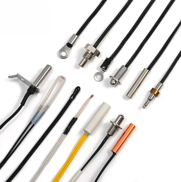
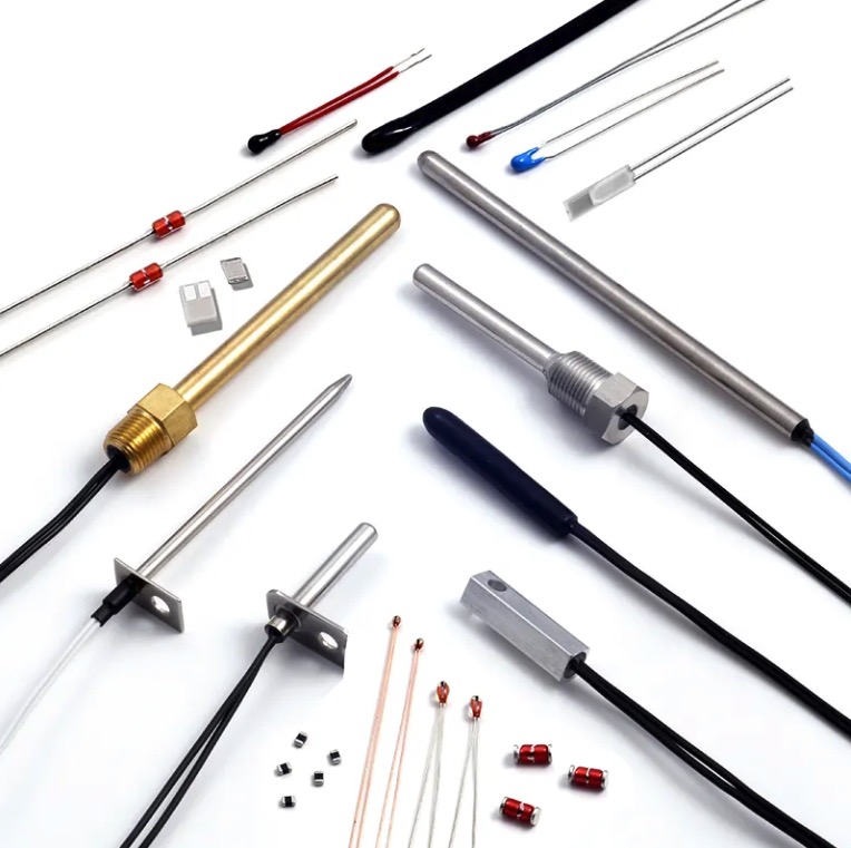
Before building a temperature and humidity sensor circuit diagram, it’s essential to understand the components involved. This section will identify and explain the necessary components required for a functional circuit. From sensors to microcontrollers, you’ll get a comprehensive overview.
Step-by-Step Guide to Building a Temperature and Humidity Sensor Circuit Diagram
6.1. Preparation and Gathering of Materials
Before diving into the actual circuit building process, adequate preparation and material gathering are crucial. This subsection will guide you through the necessary steps to ensure a smooth and successful build.
6.2. Connection and Wiring of Components
Once you have everything prepared, it’s time to start connecting and wiring the components. This step-by-step guide will walk you through the process, ensuring correct connections and minimizing errors.
6.3. Testing and Calibration of the Circuit
After the circuit is fully assembled, testing and calibration are vital to ensure accurate temperature and humidity measurements. Learn the best practices for testing and calibrating your circuit, allowing for precise and reliable readings.
Best Practices for Optimizing Temperature and Humidity Sensor Circuit Diagrams
In this section, we will explore some essential tips and techniques for optimizing temperature and humidity sensor circuit diagrams. From layout considerations to noise reduction methods, discover the best practices to enhance the performance of your circuit.
Conclusion
Congratulations! You’ve reached the end of our comprehensive guide on temperature and humidity sensor circuit diagrams. We hope this article has provided valuable insights and knowledge that will assist you in building, optimizing, and troubleshooting these circuits. Start applying what you’ve learned and embark on your journey towards mastering temperature and humidity sensors!
Temperature and humidity sensor circuit diagram is the key to accurately measuring and monitoring environmental conditions. With this comprehensive guide, learn how to build and optimize these circuits effectively. Get started today!


